Analog electronics
1. Network Analysis with d.c. Source
1.1. Model for a Battery:
: To discuss the model for the battery, consider a
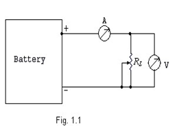
variable load resistance RL connected to the output terminals of the battery as shown in figure 1.1. Voltage across the load resistance is measured with the help of a voltmeter V. The current flowing through the load resistance RL is measured with the help of an ammeter connected in series with it. By varying the load resistance, the current I flowing through and the voltage across the load resistance RL is measured. A graph is plotted between the current I and voltage V as shown in figure (1.2). This is a straight line which cuts at V0 to the Y-axis and at I0 to the X-axis.
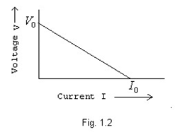
The equation for the straight line is of the form y=mx+C ,
V0
where m =− , is the slope of the curve
I 0
and C =V0 , is the intersect to the Y-axis.
V 0 V0
Thus V = −  I + V 0 ;
  has the dimension of resistance represented by R0.
I 0 I 0
This equation will be V = V 0 − R 0 I ------ (1.1)
The equivalent circuit of the equation (1.1) is given in figure (1.3).
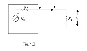
From this circuit, it is clear that the practical battery may be represented by a voltage source V0 and a resistance R0 in series with it. The resistance R0 is known as internal resistance, output resistance or source resistance of the battery.
Now put I = 0, i.e., the load resistance is removed from the circuit, then V = V0 and V0 is called as the open circuit voltage of the source. It is in fact the terminal voltage when no current is drawn from the source. The open circuit voltage when measured with a voltmeter will draw certain amount of current from the source. Thus open circuit voltage should be measured with an ideal voltmeter. Similarly, one more conceptual quantity called the short circuit current may be defined as the current flowing from the battery, when the external terminals of the battery are short circuited. The short circuit V0 current I0 will be equal to , since V = 0. This current can only be measured with an
I 0
ideal current meter. The ratio of open circuit voltage V0 to the short circuit current I0 is known as internal resistance of the battery.
From the model of the battery the following inferences can be drawn:
(i) If a load resistance RL is connected to a battery (fig. 1.4), then
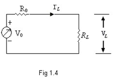
the load current IL is given by:
V 0
I L =  ------ (1.2)
(R 0 + RL )
The output voltage VL is given by:
 V0RL = V0 ------ (1.3) VL = I L RL = (R0 + RL ) (1 + R0 )
RL
 R 0 → 0 or R0 << RL , then VL = V0 ; the
From this equation it clear that if
R L
source will behave like an ideal voltage source. That is the source will said to be a good source if the internal resistance of the source is small enough than the load resistance. The ideal voltage source may be defined as follows:
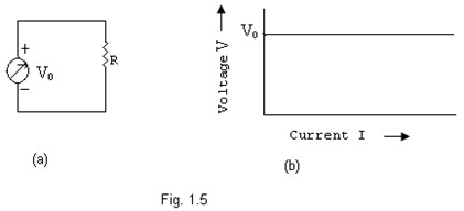
Ideal voltage source: An ideal voltage source is that source which provides a constant potential difference between its terminals, irrespective of the current drawn from it. An ideal voltage source is represented in figure 1.5(a) and it’s V – I relationship in figure 1.5(b).
(ii) Rewriting the equation (1.2), we get:
I L = ------ (1.4)
 R
R
(1 + ) (1 + )
0 R 0
It can be understood from this equation that the load current IL will be equal to the short
 RL → 0 or RL << R 0 ; the source will behave like an ideal circuit current, if the
R0
current source. That is the voltage source will act as a good current source if the source resistance is large enough than the load resistance. The current source is represented as short circuit current I0 and a source resistance R0 in parallel with it (fig.1.6). The ideal current source may be defined as follows:
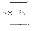 Fig. 1.6
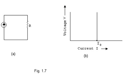
Ideal Current Source: An ideal current source is one which delivers a constant current in the circuit irrespective of the load connected to it. The V-I relationship of the ideal current source and its symbolic representation are shown in figure 1.7.
 |
(iii) Sometimes it becomes useful to transform or convert a voltage source into its equivalent current source or vice-versa. We equate the current flowing through the load resistance connected to both the circuits shown in fig. 1.8.
|

 From Current equivalent circuit I L = 0 0 L
(R 0 + R L )
V
 Equating these equations we have V0 = R0 I 0 or I 0 = 0
R 0
It is, therefore, concluded that the voltage source V0 with a series resistance R0 may be transformed to its equivalent current source I0 and the resistance R0 in parallel
 V 0 with it. The value of current source I0 is given by I 0 = . Similarly, a current source R 0
I0 with a resistance in parallel with it may be transformed to voltage source V0 and a resistance R0 in series with it. The value of voltage source is given by V0 = R0 I 0 .
Example 1.1 A variable load resistance is connected to the terminals of a battery. When the current flowing in the load is 2A, the voltage across the load resistance is 5.8 volts; also when the load current is 5A, the voltage across the load resistance is 5.5volts. All the measurements are made using ideal meters.
Find: (a) Open circuit voltage and source resistance of the battery.
(b) Equivalent current source model of the battery.
Solution: (a) Let V0 and R0 are the open circuit voltage and source resistance of the battery respectively. As per statement of the problem:
(i) 
 In the first case 5.8 volts = 2A RL or RL = 2.9 Ω; V0 RL = 5.8 or V0 .(2.9) = 5.8 or V0 = 2R0 + 5.8
and
(R0 + RL ) (R0 + 2.9)
In the second case 5.5volts = 5A.RL' or RL' = 1.1 Ω;
 and V0 RL' ' = 5.5 or V0 .(1.1) = 5.5 or V0
(R0 + RL ) (R0 +1.1)
From these two cases: V0 = 6 volts & R0 = 0.1 Ω.
= 5R0 + 5.5
(ii) The current source equivalent of the values calculated above is given in figure
(1.9). The value of current source I0 = 6 x .1 = 60 mA
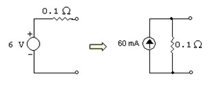
Fig. 1.9