Analog electronics
1. Network Analysis with d.c. Source
1.2. Network analysis
The analysis of the electric circuits or networks which are formed by interconnecting the sources of electrical energy with other elements like resistances will now be discussed. Here consider the source of electrical energy as d.c. source which does not change with time. Simple circuits may be analyzed using well known Ohm’s law. Kirchoff’s laws may, however, be used to analyze more complicated circuits. Kirchoff presented two laws namely (i) Kirchoff’s Current law (KCL) & (ii) Kirchoff’s voltage law (KVL). These laws are the generalization of Ohm’s law.
1.2.1 Kirchoff’s Current Law (KCL): This law is applicable to any node or junction of electric circuit. The node or junction in an electric circuit is defined as the point where more than two elements meet. This law states that the algebraic sum of currents entering to any node of an electric circuit is zero. The total current entering to a node must be equal to that leaving it. The sign convention for this law is generally assumed that the current entering the node is positive while the current leaving the junction is negative. Mathematically, the law is ∑I = 0 .
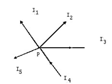
Fig. 1.10
This law may further be illustrated by considering the junction P shown in figure 1.10. I1, I2 & I5 are the currents entering the junction which are assumed to be positive while I3, & I4 are negative, as these are leaving the junction.
So I1 + I 2 − I 3 − I 4 + I 5 = 0
or I 1 + I 2 + I 5 = I 3 + I 4
Current leaving = Current entering
1.2.2 Kirchoff’s Voltage Law (KVL): This law is applicable to a mesh or loop of an electric circuit. A mesh or loop is defined as a closed circuit. The Kirchoff’s Voltage law states that the algebraic sum of all the voltage drops in any loop is zero.
The sign convention for applying the KVL to the closed loop is that an arbitrary reference direction of current in the clock wise direction is assumed. The associated reference direction across the resistances is marked positive at the tail of the arrow and negative to head of the arrow. If there is a voltage drop in the circuit, it is assumed to be positive while it is assumed to be negative for the voltage rise in the circuit.
For applying the KVL, we consider a closed circuit given the figure 1.11
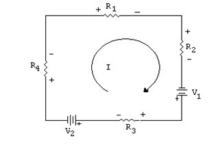
Fig 1.11
From this figure: R I1 + R2 I −V1 + R I3 +V2 + R I4 = 0 or (R1 + R2 + R3 + R4 )I =V1 −V2
From this equation it is clear that any unknown quantity may be calculated if rest of the quantities is known.
Example 1.2 A voltmeter having the sensitivity of 20KΩ/V is used to measure the voltage across 50KΩ resistance in the circuit shown in the figure (1.12). The voltmeter is used in 50volts range.
Calculate (a) the reading of the voltmeter,
(b) percentage error in the reading with respect to true value.
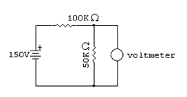
Fig. 1.12
150x50K
Solution: The true voltage =  = 50 volts (100 + 50)K
Resistance of the voltmeter in 50volt scale is
Rg =50x20K = 1MΩ
When the voltage across 50KΩ resistance is measured, the voltmeter resistance Rg will also come in parallel with 50KΩ resistance. So the voltage will be measured across the parallel combination and not across 50 KΩ resistance. Due to which there will be an error.
Reading of the voltmeter Vm will be equal to the voltage across the parallel combination. Resistance of the parallel combination is given by:
50Kx1M
Req =  = 47.6KΩ
(1M + 50K)
Voltmeter reading Vm =  = 48.36volts
% error in the reading =  = 3.28%