Analog electronics
2. Two – Port Network
2.2. Admittance Parameters
: The admittance parameters of a linear two port network may also be defined in the similar fashion as the impedance parameters discussed above. In the admittance parameters, variables V1 & V2 are assumed independent variables and I1 & I2 as the dependent variables. The dependent variables I1 & I2 may be defined as a linear function of Independent variables V1 & V2 as
I1 = f1 ( V1, V2 )
I2 = f2 ( V1, V2 ) ------- (2.5)
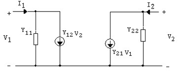
and I1 =Y11V1 +Y12V2
I2 =Y21V1 +Y22V2 ------- (2.6)
In the matrix form it is given by :
I1 Y11 Y12 V1
= ------ (2.7)
I 2 Y21 Y22 V2
Where Y’s are the admittance (conductance for d. c.) parameters, which may be defined as :
Y 11 =, is the input admittance when output is short
V 2 = 0
 circuited or short- circuit input admittance.
Y 12 = , is the reverse transfer admittance when input is
V 1 = 0
short circuited or short circuit reverse transfer admittance.
Y 21 =, is the forward transfer admittance when output is
V 2 = 0
short circuited or short circuit forward transfer admittance.
and Y 22 =  , is the output admittance when input is short
V 1 = 0
circuited or short circuit output admittance.
These Y – parameters are also called as short circuit parameters as given in the network either input or output is shorted. The equivalent circuit of the network using Y- parameters is given in figure2.3.