
Analog electronics
3. Networks with Time Varying Sources
3.2. Sinusoidal Signal applied to different elements
When an A.C. signal E t = EmSinωt is applied to a simple resistance, according to Ohm’s Law one may obtain the instantaneous value of the current flowing through the circuit as:
E t E m
 I t
I t = = Sin ωt
R R
= I m Sin ωt (Im is the peak value of current)
Thus the current wave form is the exact replica of the voltage, i.e., both are in the same phase. But when an A.C. source is applied to any combination of resistance, inductance and capacitance, we get the current and voltage are having certain phase difference. Phase relation between the current flowing through and voltage applied across the circuit may best be understood if the Impedances and reactances are represented on the complex plain.
When an A.C. signal E t = E m Sin ωt is applied across an inductance L, the instantaneous value of the current flowing through the circuit is given by:
1 1
I t =
 ∫ E
∫ E .t dt =
 ∫ (E m sin ωt).dt
L L
 = E m . − cos ωt = E m sin ωt − π
 ------ (3.18)
L ω ωL 2
It is clear from this equation that the current is lagging by an angle of 90 o with the voltage. The quantity Em is known as the peak value of the current. It is
ωL
customary to represent the magnitude as well as the phase relation between the voltage and the current in a graphical form. Such a graphical form is known as phasor diagram.
 The phasor diagram is generally represented on the complex plain, as shown in figure (3.3). When a quantity coincides with the X-axis (real axis), it is known as real quantity. The quantity on X-axis when multiplied by j (( j = −1) , makes it purely imaginary quantity. It rotates by an angle of 90o in the anti-clock wise direction. However, when the real quantity is divided by j or multiplied by (– j) it rotates in the clock wise direction by 90o.

Fig. 3.3
From the equation (3.18), it is clear that the voltage E, when divided by ωL , the correct magnitude of the current is obtained. In order to rotate the phase by – 90 o the magnitude of current is further divided by j as:
E π
I =  and ∠I =∠E −
 jωL 2
jωL 2
The imaginary quantity ( jωL) is called the inductive reactance of the inductance L.
The current is lagging behind the voltage by an angle of 90o as shown in figure (3.4). This is the phase relation between the current and voltage.

I
Fig. 3.4
1 − j
Similarly the reactance of a capacitance is  or
or  , which is also an jωC ωC
imaginary quantity represented on the imaginary axis. The current flowing through the capacitance C when an A.C. signal of voltage E is applied across the capacitance is given
E
by: I == jωCE
 (1 jωC)
or 
The current is 90o ahead by the voltage as is shown in figure (3.5).
I

E
Fig. 3.5
 The impedance of a series combination of a resistance R and an inductance L is given by Z = R + jωL or Z = R 2 + (ωL) 2
The phase angle θ the impedance makes with the resistive component R is given by: θ= tan−1 (ω L) R
L) R
 The impedance Z is written as: Z = Z .∠tan−1 (ω
 L)
L)
R
The current flowing through this combination is given by:
 I = E = E or ∠I =∠E − tan−1 (ω
 L)
L)
Z R + jωL R
The current is lagging behind with the voltage by an angle tan−1 (ω L).
L).
R
The impedance of a series combination of a resistance R and an capacitance C is
 1 2 2 given by Z = R +
  or Z = R + (1 ωC) jωC
The phase angle θ the impedance makes with the resistive component R is given
by: θ= tan−1 (  1 )
1 )
ωCR
 The impedance Z is written as: Z = Z .∠tan−1 (
  1 ) ωCR
The current flowing through this combination is given by:
E E E.( jωC) π −1
 I = = = or ∠I =∠E +
  − tan (ωCR)
Z R + (1/ jωC) 1+ jωCR 2
The phase difference between current and voltage is − tan−1 (ωCR) .
Example 3.5 An A.C. signal of 20 volts and frequency 200Hz as applied to a circuit consisting of 10 mH inductance and 10 Ω resistance in series with it. Find the magnitude and phase of the current.
Solution: The impedance Z of series combination is given by:
Z = R + j2.πf L. = 10 + jx2x3.14 x200 x10 x10 −3 = 10 + jx12.56
 Z = (10) 2 + (12.56) 2 =16Ω and θ= tan−1 (
 ) = 51.47 0
Current  =1.25amp
Fig. 3.6
And phase difference ϕ=∠I −∠V =−51.47 0
Example 3.6 Consider a series R – C circuit having R = 1.5KΩ and C = 0.2µF is excited by a sinusoidal signal of 20 volts and frequency 2 KHz. Find the magnitude and phase of the current.
Solution: The impedance of the R – C circuit is given by: j j
 Z = R −ωC =1500 − 2x3.14x2000x0.2x10−6
j104
=1500 − =1500 − j398.1
25.12
 Z = (1500) 2 + (398.1) 2 =1552Ω

So Z =1552Ω∠−14.860

Fig. 3.7
The phasor diagram is given in figure 3.7.
Example 3.7 Consider a sinusoidal signal of peak value of 20 volts with frequency of 2000 radians/sec is applied to a circuit shown in figure (3.8). L=20 mH, C1=C2=0.2 µF, R=100 Ω . Calculate the total current I and the currents I1 & I2 in the two branches.
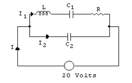
Fig. 3.8
Solution: Impedance Z1 of the series branch is given by:
Z

Current I1 in this series branch is given by:
20 20 0
 I1 = = 0 = 8.13mA∠87.67 Z1 2.46KΩ∠−87.67
− j − j − j104
 Impedance of the capacitor branch Z 2 =ωC2 = 2000x0.2x10−6 = 4
|
|
=−2500 j = 2.5KΩ∠−π/ 2 |
|
Current I2 in this branch is given by: |
|
I / 2
/ 2
Admittance of Z1 & Z2 impedances is given by:
1 1 1 1 1
Y  = = + = 0 +
Z Z1 Z 2 2.46KΩ∠−87.67 2.5KΩ∠−π/2
= 0.00041∠87.67 0 + 0.0004∠π/2
= [0.000017 + j0.00081]+[ 0.j 0004] = 0.000017 + j0.00081
= 0.00081∠88.80
Total impedance Z 
Total current I 